Electrocardiogram
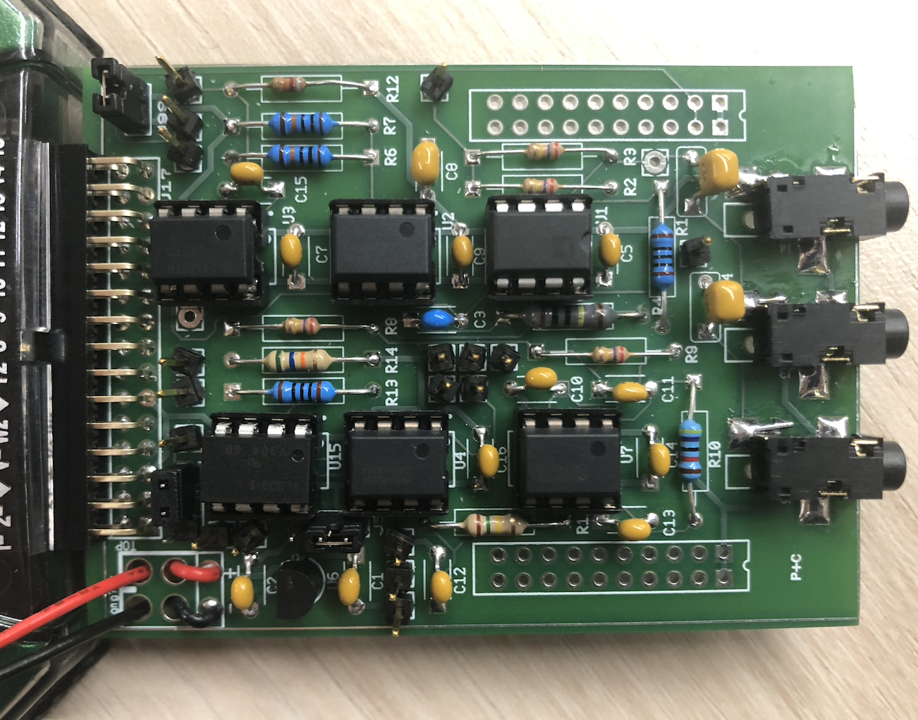
ECE Fundamentals III (ECE3750) Final Project Made by Max Titov, Quentin Olsen, and Bhargav Moosani
Project Overview
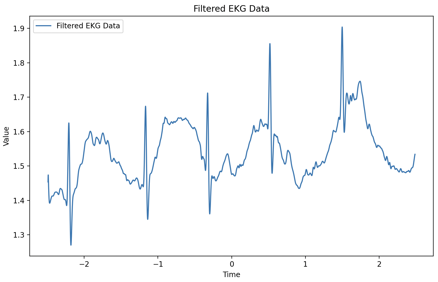
The goal of the project was to create a functional electrocardiogram (EKG). We designed five electrical subsystems, with each team member taking on specific responsibilities. An example of a recorded pulse can be seen below:
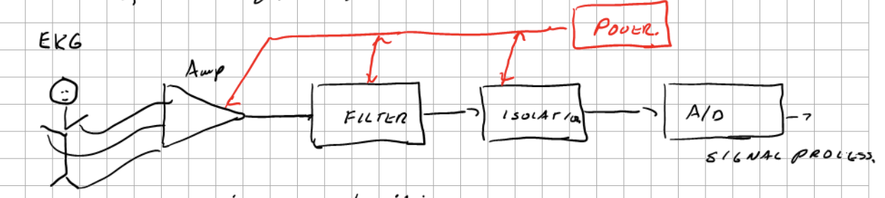
The electrical pulses from a subject’s wrist were processed through an in-amp and integrator system, followed by a filter to remove high frequencies. The filtered signal then passed through an isolator for protection against electrical failures, and finally underwent digital signal processing for a clean output. The signal path can be seen in the diagram below.
There were five electrical subsystems: power supply, instrumentation amplifier, anti-alias filter, and the isolator. They are described in detail below.
Power Supply
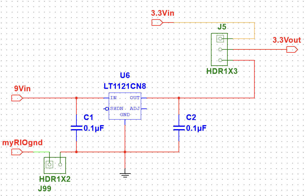
The point of the power supply is to set VCC, for which most integrated circuits on the board will use, to 3.3V. This is implemented with two different sources. The first is done by stepping down a 9V voltage from an auxiliary battery, using a voltage regulator (U6). The second from the Analog Discovery 2’s DC voltage supply. This directly puts out 3.3V and allows isolated system tests.
Instrumentation Amplifier
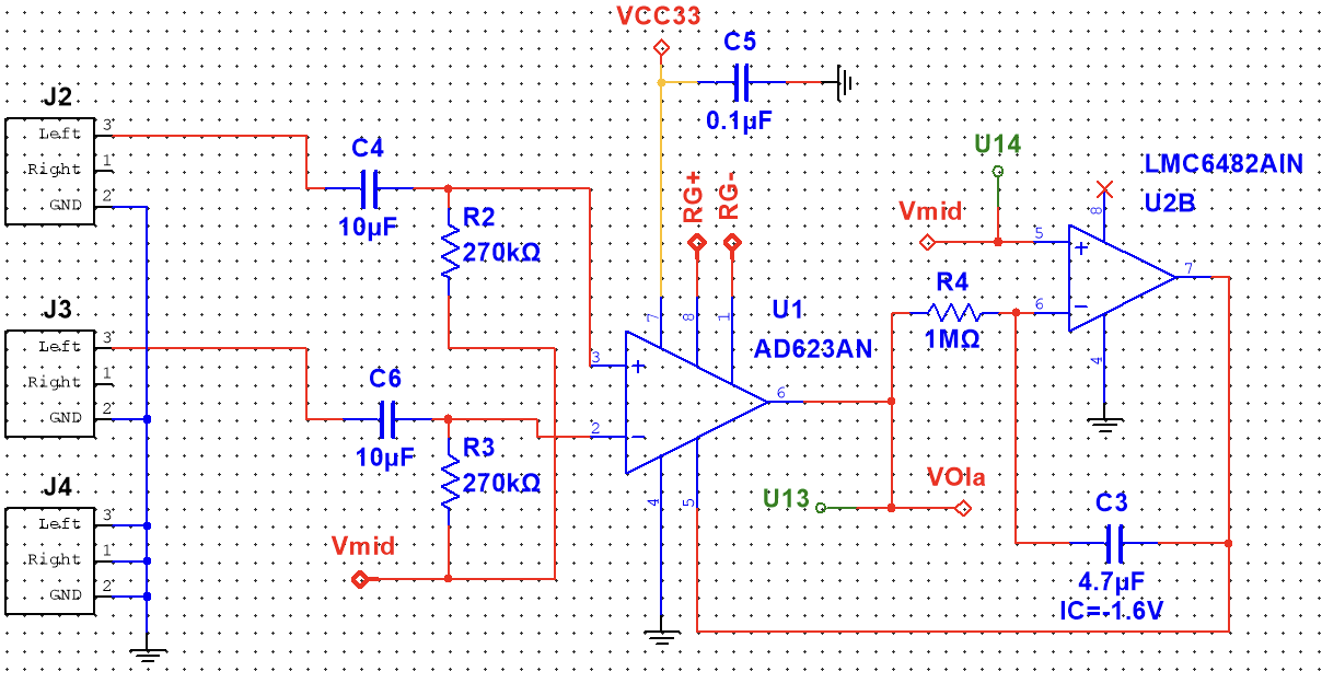
The first step of the signal processing from the raw input is the In-Amp. EKG signals can be easily contaminated by various types of noise, including electromagnetic interference and movement artifacts. In-Amps are designed to reject common-mode noise, which is noise that appears identically on both signal inputs. The difference between the two inputs then gets amplified to a more usuable range.
Anti-alias Filter
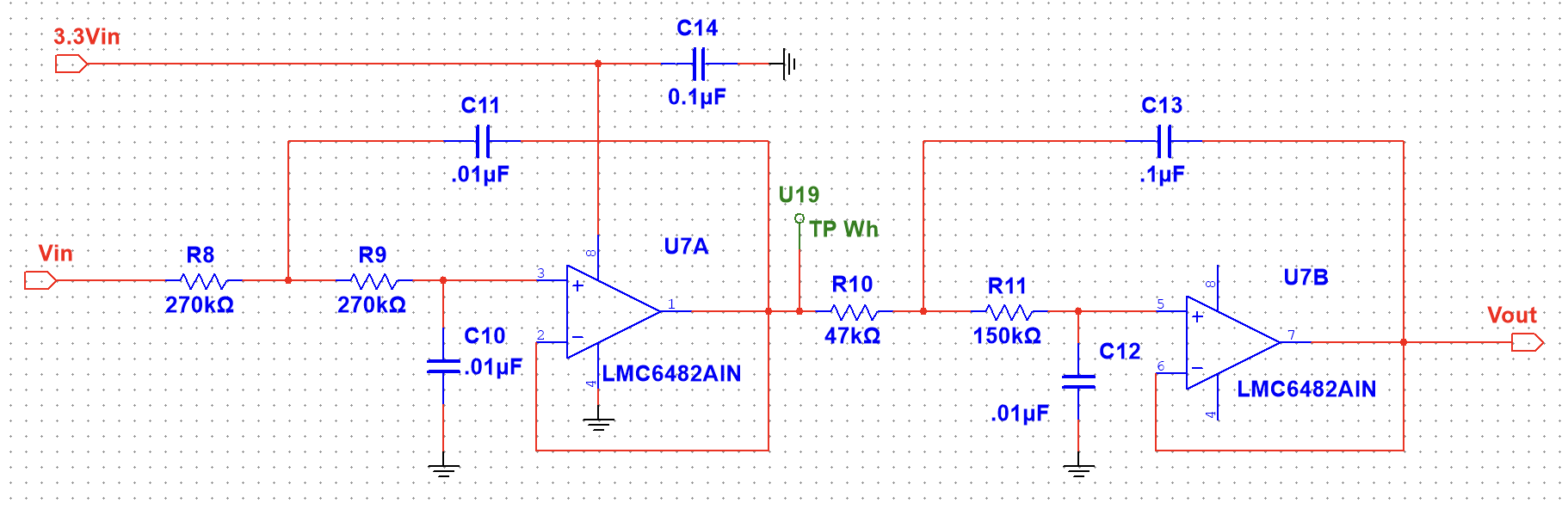
The anti-aliasing filter seen below is a 4th order Butterworth filter, which is used to attenuate high frequency signals and prevent as much rippling as possible in the pass-band. The filter is made up of two cascaded 2nd order low-pass filters. Since our filter’s total response is 4th order low-pass, we’ll have a -80dB/dec roll-off in our frequency response at the corner frequency.
Isolator
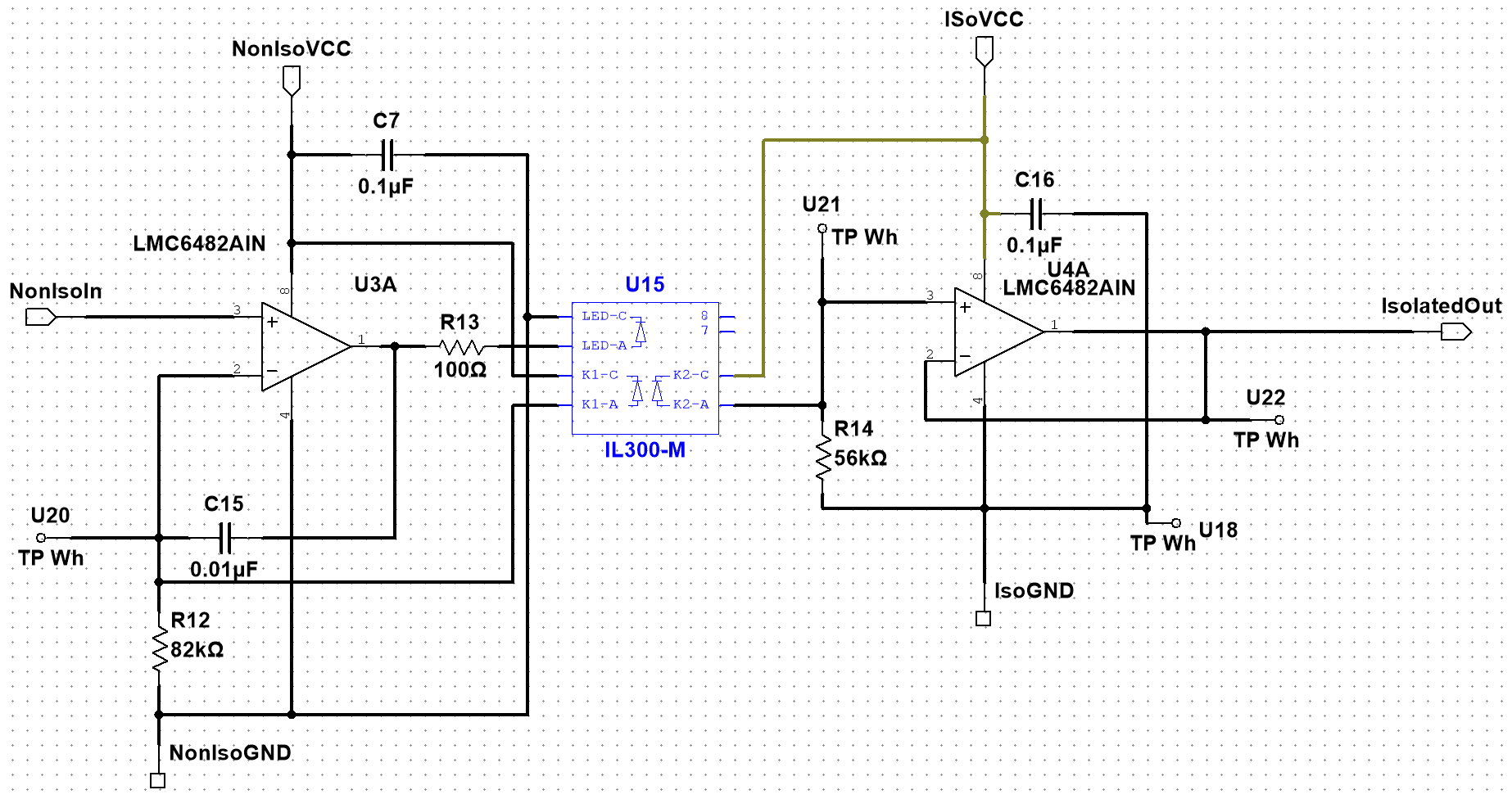
The isolator is used to protect the device and patient in case of device failure. It separates the AD2 and battery power sources while keeping the signal at the same voltage.
Setup
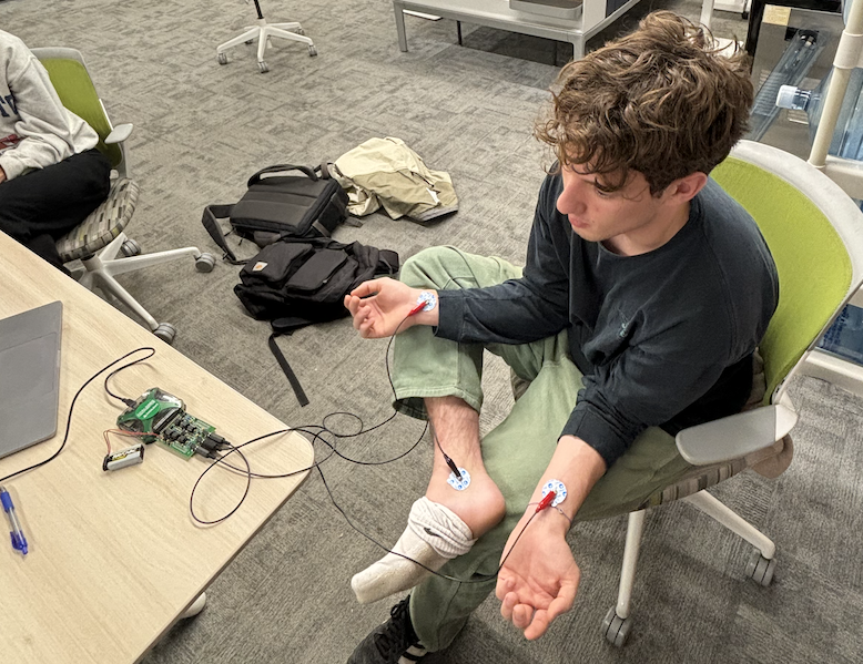
The setup consisted of connecting three probes: one on each wrist and a ground connection to the ankle. A picture of the setup can be seen below.
Results
With the setup shown above, we recording the following EKG signal on Waveforms software.
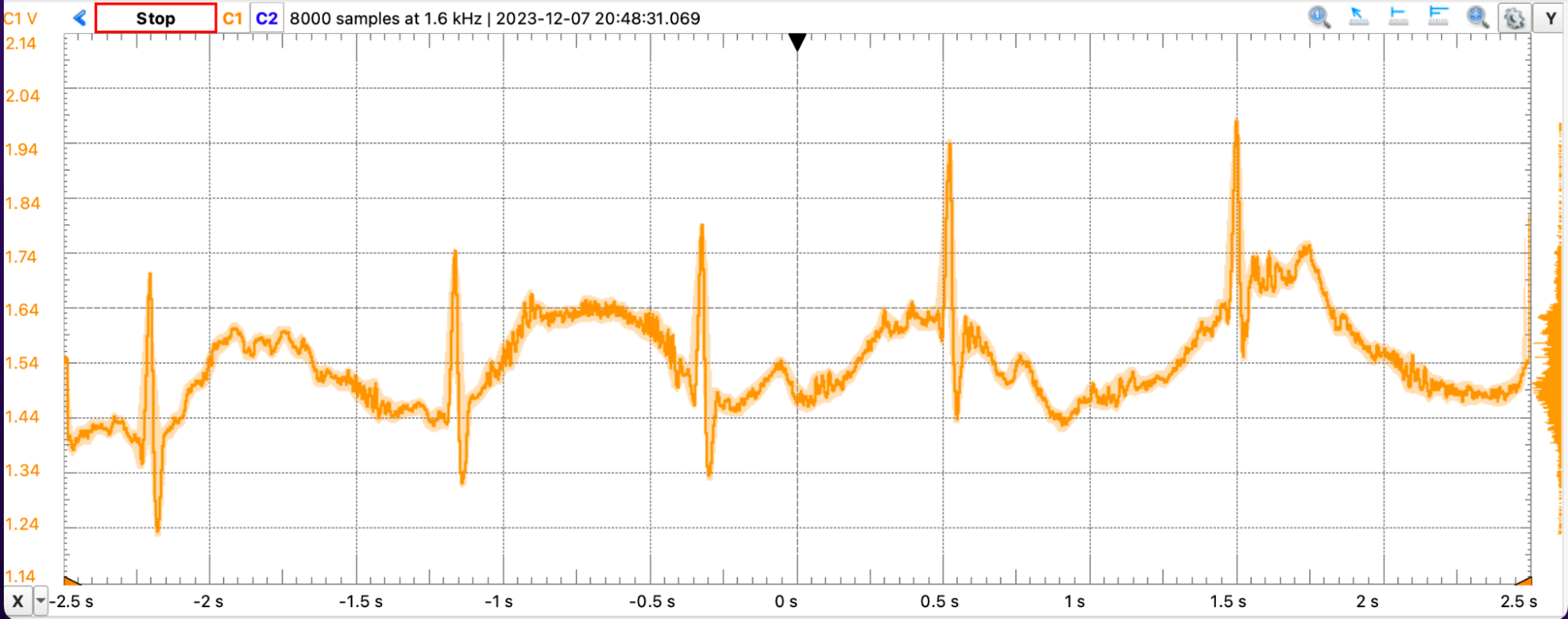
There was a lot of noise in the signal caused by interference caused by ambient electromagnetic waves from nearby electronics operating at 60Hz. To clean the data from this noise, so we applied a finite impulse response (FIR) filter to the data. The results are shown below.